What is a UML use case diagram?
A UML use case diagram shows external actors, their goals and the system boundary. It summarizes who interacts with a system and the behavior they need from it.
The question this diagram answers: Which goals do external actors pursue through the system?
Explore all 14 UML diagram types. Interaction diagrams are a specialized subset of UML behavior diagrams.
When to use a use case diagram
Use a use case diagram early in requirements discussions to establish scope and participants. It summarizes goals and relationships, while detailed scenarios explain the steps and exceptions.
Main elements and notation
Actor
An actor is an external role interacting with the subject. It may be a person, another system or a device, rather than a particular individual.
Use case
An ellipse names behavior valuable to an actor. Prefer goal-oriented names such as Complete checkout.
System boundary
The enclosure identifies the subject being described; actors remain outside it.
Association
A line connects an actor to a use case in which that role participates.
Include
An include dependency points from the including use case to the included use case.
Extend
An extend dependency points from the extending use case to the extended use case. Extension points identify where additional behavior may be inserted.
A real example in UXXU
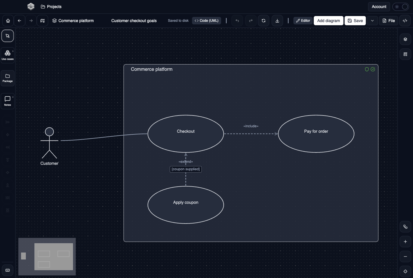
Actual UXXU Desktop screenshot of an illustrative commerce project. Open the full-size example.
The customer interacts with checkout inside the commerce system boundary. Payment and coupon use cases distinguish reusable required behavior from optional extension behavior. Read dependency direction carefully rather than treating the drawing as a chronological flowchart.
Draw it in UXXU
Open an editable project, add a Code (UML) diagram, and choose Use case as its UML diagram type.
- Add a system boundary with a clear subject name.
- Place actors outside it and goal-oriented use cases inside.
- Connect actor participation with associations.
- Add include or extend relationships only when their meaning fits, and describe the extension condition or point where needed.
Select an element or connector to edit its properties. Use editable text for advanced notation where appropriate. Move and resize elements to keep labels readable; save your workspace and reopen the diagram to review the result. Editing availability depends on your plan or desktop licence.
Common mistakes and review checks
Do not use include and extend simply to show which screen comes next. Use activity or sequence diagrams to describe an individual scenario in order.
Before sharing, check that names are consistent, connector directions are intentional, and labels do not cover the notation they describe. Ask another reader to answer the question at the top of this guide using only the diagram.
Choose the next view
UXXU focuses on visual authoring. These guides do not imply executable UML models, automatic semantic validation, or shared UML model-element references across diagrams. PlantUML import/export compatibility is separate from visual notation coverage. Check the download page for published desktop releases.
For normative UML definitions, consult the OMG UML 2.5.1 specification.