What is a UML state machine diagram?
A UML state machine diagram shows the states of a subject and the event-driven transitions between them. It explains how behavior depends on the current state.
The question this diagram answers: How does one entity react to events throughout its lifecycle?
Explore all 14 UML diagram types. Interaction diagrams are a specialized subset of UML behavior diagrams.
When to use a state machine diagram
Use a state machine to explain behavior that depends on current state: an order lifecycle, a connection protocol or a device controller. Its focus is the state of a subject, rather than a sequence of workflow tasks.
Main elements and notation
State
A rounded rectangle represents a situation in the lifecycle. Names such as Draft or Paid communicate a condition.
Transition
A directed connection describes a possible change. The conventional label is trigger [guard] / effect.
State behaviors
Entry, do and exit behaviors describe work associated with a state. Internal transitions and deferred events add detail without introducing another visible state.
Composite states and regions
Nested states organize detail. Separate regions can represent concurrent state configurations.
Pseudostates
Initial, choice, junction, history, fork and join symbols organize transition behavior; they are not ordinary stable states.
Connection points
Entry and exit points, and submachine connection references, make boundary crossings explicit.
A real example in UXXU
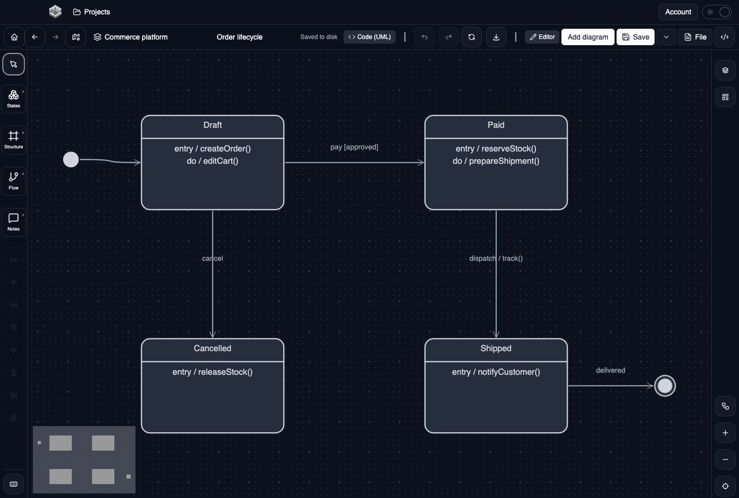
Actual UXXU Desktop screenshot of an illustrative commerce project. Open the full-size example.
The order lifecycle shows Draft, Paid, Cancelled and Shipped. Read an outgoing transition as an event that may occur while the order is in its source state, subject to its guard. Compare shipping and cancellation paths to discuss which changes should remain possible after payment.
Draw it in UXXU
Open an editable project, add a Code (UML) diagram, and choose State machine as its UML diagram type.
- Add the main lifecycle states and an initial pseudostate.
- Draw transitions and edit triggers, guards and effects.
- Add state behaviors, internal transitions or deferred events in the properties editor when relevant.
- For a nested lifecycle, create the composite state and its connection points, then review boundary attachments.
Select an element or connector to edit its properties. Use editable text for advanced notation where appropriate. Move and resize elements to keep labels readable; save your workspace and reopen the diagram to review the result. Editing availability depends on your plan or desktop licence.
Common mistakes and review checks
Do not name every state after a task. A transition effect and a do behavior have different lifecycle semantics. UXXU authors their notation; it does not execute the state machine.
Before sharing, check that names are consistent, connector directions are intentional, and labels do not cover the notation they describe. Ask another reader to answer the question at the top of this guide using only the diagram.
Choose the next view
UXXU focuses on visual authoring. These guides do not imply executable UML models, automatic semantic validation, or shared UML model-element references across diagrams. PlantUML import/export compatibility is separate from visual notation coverage. Check the download page for published desktop releases.
For normative UML definitions, consult the OMG UML 2.5.1 specification.