What is a UML composite structure diagram?
A UML composite structure diagram shows the internal parts, ports and connectors of a structured classifier. It explains how internal roles collaborate behind an external boundary.
The question this diagram answers: How do the internal parts of a classifier collaborate through its boundary?
Explore all 14 UML diagram types. Interaction diagrams are a specialized subset of UML behavior diagrams.
When to use a composite structure diagram
Use a composite structure diagram when a component box hides an important internal design. It explains the roles of internal parts, the external interaction points, and the connectors between them.
Main elements and notation
Structured classifier
The enclosing classifier defines the context for the internal structure.
Part
An internal part is a role, often written roleName: Type. Its multiplicity can describe several instances playing that role.
Port
A boundary square represents an interaction point on the classifier or one of its parts.
Delegation connector
Delegation relates an external interaction point to the internal part that handles it.
Assembly connector
Assembly connects compatible roles or interfaces of collaborating parts.
A real example in UXXU
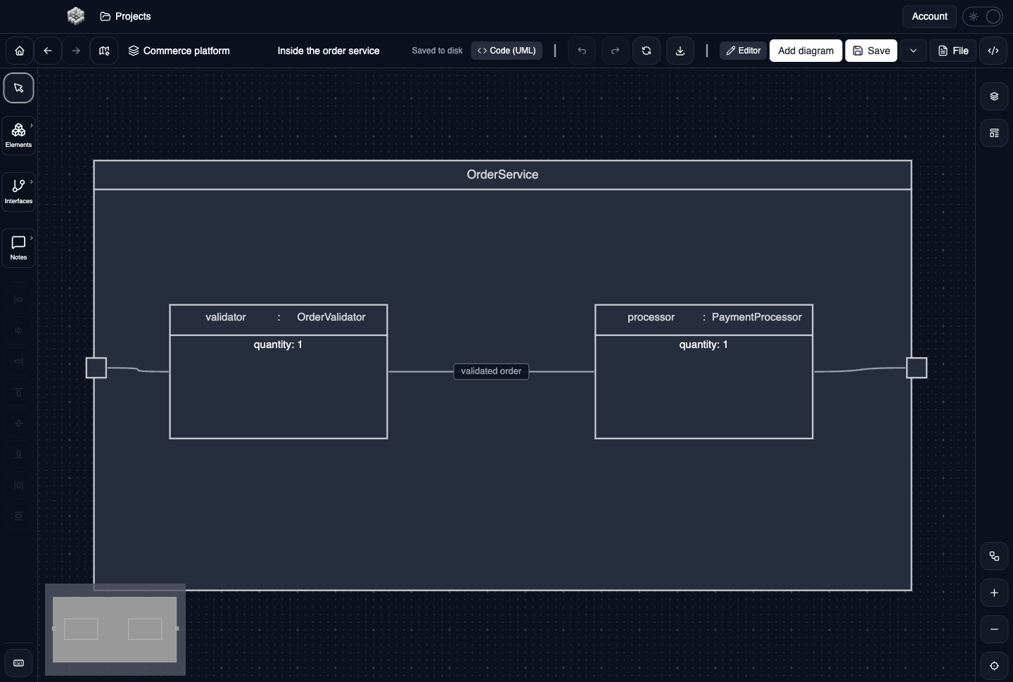
Actual UXXU Desktop screenshot of an illustrative commerce project. Open the full-size example.
The OrderService example contains validator and processor parts. Read from a boundary port into the enclosed structure to understand which internal role receives a request and how the roles collaborate. The enclosure supplies context; it is not merely decorative grouping.
Draw it in UXXU
Open an editable project, add a Code (UML) diagram, and choose Composite structure as its UML diagram type.
- Create the structured classifier and size it to leave room for its internal parts.
- Add and name the parts inside the classifier; describe each role and type.
- Place ports on the relevant boundaries.
- Use delegation for boundary-to-internal handling and assembly for the appropriate collaboration between parts.
Select an element or connector to edit its properties. Use editable text for advanced notation where appropriate. Move and resize elements to keep labels readable; save your workspace and reopen the diagram to review the result. Editing availability depends on your plan or desktop licence.
Common mistakes and review checks
Do not draw a part outside its owning structure and expect the visual relationship to remain clear. Check port ownership after moving or resizing the container.
Before sharing, check that names are consistent, connector directions are intentional, and labels do not cover the notation they describe. Ask another reader to answer the question at the top of this guide using only the diagram.
Choose the next view
UXXU focuses on visual authoring. These guides do not imply executable UML models, automatic semantic validation, or shared UML model-element references across diagrams. PlantUML import/export compatibility is separate from visual notation coverage. Check the download page for published desktop releases.
For normative UML definitions, consult the OMG UML 2.5.1 specification.