What is a UML component diagram?
A UML component diagram shows software components, the interfaces they provide or require, and their dependencies. It helps explain a modular software design.
The question this diagram answers: Which software components provide and require which contracts?
Explore all 14 UML diagram types. Interaction diagrams are a specialized subset of UML behavior diagrams.
When to use a component diagram
Use a component diagram to review a modular design, identify service dependencies, or discuss interfaces across implementation boundaries. Choose a consistent level: a deployable service and a small library module are different scales of abstraction.
Main elements and notation
Component
A named component identifies a modular unit with a defined contract. The component icon or keyword distinguishes it from a plain classifier.
Provided interface
The lollipop symbol represents an interface offered by a component.
Required interface
The socket represents an interface needed by a component. Connecting compatible provided and required interfaces shows assembly.
Port
A small boundary square identifies a distinct interaction point. Name it when one component has several contracts.
Dependency
A dashed arrow points from the dependent element toward the element it needs.
A real example in UXXU
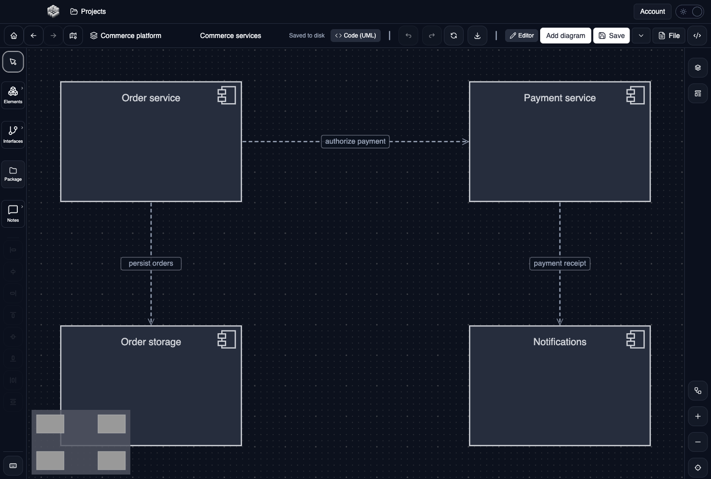
Actual UXXU Desktop screenshot of an illustrative commerce project. Open the full-size example.
The commerce example separates ordering, payments, persistence and notifications. Follow dependencies from the consuming component to the supplier, then ask which interface would let one component change without forcing all the others to change.
Draw it in UXXU
Open an editable project, add a Code (UML) diagram, and choose Component as its UML diagram type.
- Add the components and give each a responsibility-focused name.
- Add interfaces or ports where a contract is important to the discussion.
- Use dependency connectors for usage and assembly connectors for the appropriate interface connections.
- Label the contracts and arrange components so dependency directions are easy to follow.
Select an element or connector to edit its properties. Use editable text for advanced notation where appropriate. Move and resize elements to keep labels readable; save your workspace and reopen the diagram to review the result. Editing availability depends on your plan or desktop licence.
Common mistakes and review checks
Do not assume a component is a machine or deployment unit. Use a deployment diagram for runtime placement, or a composite structure diagram to look inside a classifier.
Before sharing, check that names are consistent, connector directions are intentional, and labels do not cover the notation they describe. Ask another reader to answer the question at the top of this guide using only the diagram.
Choose the next view
UXXU focuses on visual authoring. These guides do not imply executable UML models, automatic semantic validation, or shared UML model-element references across diagrams. PlantUML import/export compatibility is separate from visual notation coverage. Check the download page for published desktop releases.
For normative UML definitions, consult the OMG UML 2.5.1 specification.