What is a UML deployment diagram?
A UML deployment diagram shows computational nodes, execution environments, deployed artifacts and communication paths. It explains where software runs.
The question this diagram answers: Where does software run, and how do runtime nodes communicate?
Explore all 14 UML diagram types. Interaction diagrams are a specialized subset of UML behavior diagrams.
When to use a deployment diagram
Use a deployment diagram to explain infrastructure placement, runtime environments, and installed software artifacts. It complements logical component design with an operational view.
Main elements and notation
Node and device
A node is a computational resource. A device represents a physical computational resource; use an appropriate name and stereotype to clarify its role.
Execution environment
An execution environment hosts software execution and may be nested inside a device or another environment.
Artifact
An artifact is a piece of information used or produced during development or operation, such as an executable package or configuration file.
Deployment
A deployment relationship places an artifact on a deployment target. Containment can also communicate placement.
Communication path
A path between nodes describes their ability to communicate. Protocol labels help clarify the intended connection.
Manifestation
A manifestation relates an artifact to the model element it implements or embodies; it differs from deploying that artifact to a node.
A real example in UXXU
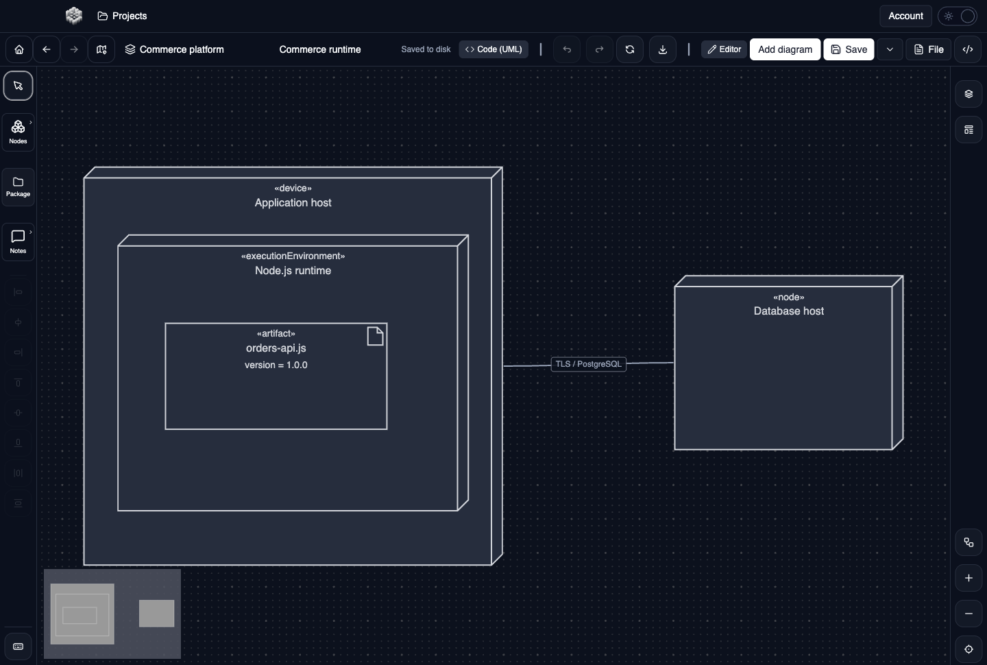
Actual UXXU Desktop screenshot of an illustrative commerce project. Open the full-size example.
The example places an order-service artifact inside a runtime on an application host and shows a database node. Read the containment from host to runtime to artifact, then follow the communication path to the database.
Draw it in UXXU
Open an editable project, add a Code (UML) diagram, and choose Deployment as its UML diagram type.
- Choose UML Deployment, rather than the separate C4 Deployment view.
- Add the host and database nodes, then nest the execution environment where appropriate.
- Place the deployed artifact in its target or draw the relevant deployment relationship.
- Connect the nodes and label their communication path with the intended protocol or purpose.
Select an element or connector to edit its properties. Use editable text for advanced notation where appropriate. Move and resize elements to keep labels readable; save your workspace and reopen the diagram to review the result. Editing availability depends on your plan or desktop licence.
Common mistakes and review checks
Do not treat a dependency between software components as proof of network connectivity. Deployment targets and communication paths should reflect the runtime architecture you intend to operate.
Before sharing, check that names are consistent, connector directions are intentional, and labels do not cover the notation they describe. Ask another reader to answer the question at the top of this guide using only the diagram.
Choose the next view
UXXU focuses on visual authoring. These guides do not imply executable UML models, automatic semantic validation, or shared UML model-element references across diagrams. PlantUML import/export compatibility is separate from visual notation coverage. Check the download page for published desktop releases.
For normative UML definitions, consult the OMG UML 2.5.1 specification.