A container view says that a Checkout API depends on an Orders store. A deployment view answers where their instances run in a particular environment. These examples help you review that mapping, using two deliberately small checkout designs and a Kubernetes mapping of the same checkout responsibilities.
Deployment is supplementary to the four C4 levels. It is not a fifth level, and a C4 container is not necessarily a Docker container. The official deployment diagram guidance describes mapping system or container instances onto deployment nodes.
Example 1: Checkout on virtual machines
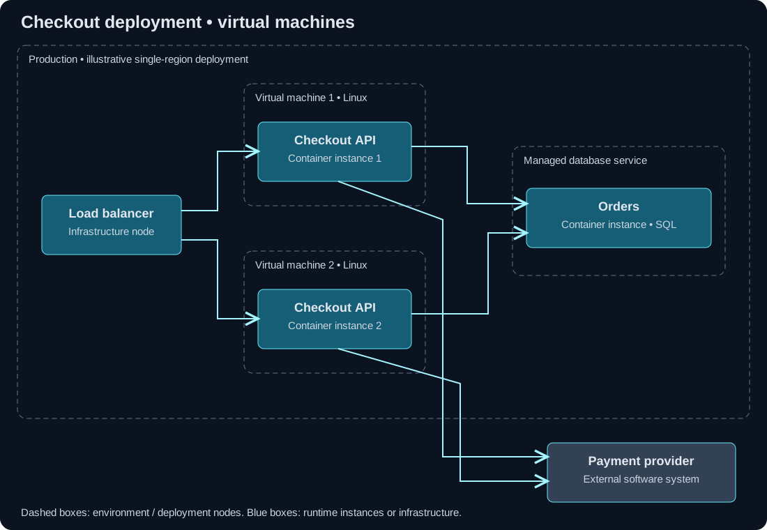
Download the editable VM deployment SVG. It is a synthetic design, not a snapshot of UXXU infrastructure. The rounded outer boundary is the production environment; nested boundaries represent deployment nodes. The two API boxes are instances of one logical container. They are not two independently owned applications.
Start at the load balancer. Follow a checkout request to either API instance, then follow the SQL relationship to the Orders database. Both instances also call the same external Payment provider. If one VM is removed, the remaining route is visible. The drawing does not prove that failover works: health checks, session handling and capacity still need evidence.
Change exercise: move from two API instances to three. Update the deployment view. The logical container view still needs one Checkout API element unless its responsibility or ownership has changed. Record the scaling policy beside the deployment rather than renaming the container “three APIs.”
Example 2: Checkout on Kubernetes
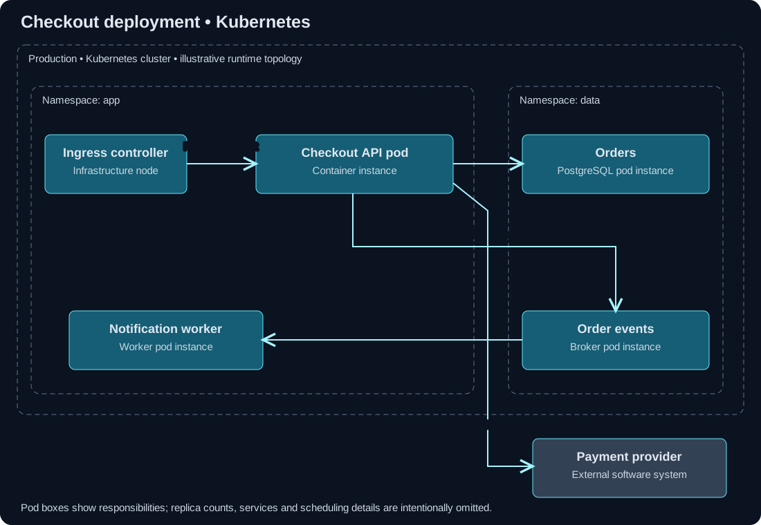
Download the editable Kubernetes deployment SVG. The API and worker run as separate workloads. Orders and Order events are shown inside the cluster’s data namespace for this example; a managed database or broker would instead sit outside that cluster boundary.
Replica counts and Kubernetes Services are omitted to focus on responsibilities. Namespace boundaries alone do not establish traffic isolation: review the relevant network policy and runtime configuration before making that claim.
Review exercise: identify the cluster boundary, the ingress path and the workload instances. Select one dependency that leaves the cluster. Ask who owns it and what happens if that connection fails. If you cannot answer from the view, write down the missing information instead of assuming every adjacent box shares an availability zone or trust boundary.
Include nodes, pods, services or namespaces when they answer your review question. A deployment diagram does not need to reproduce every object in a cluster inventory.
Example 3: Checkout on managed functions
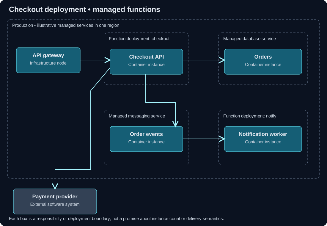
Download the editable serverless deployment SVG. This alternate design maps the Checkout API and Notification worker responsibilities to separate managed function deployments. It maps the Orders and Order events containers to managed persistence and messaging services.
The event path separates post-order notification from payment authorization. The arrows describe intended interactions; they do not guarantee delivery semantics. Review how the worker handles a repeated event, where failed deliveries go and which identifier lets operators trace one order through the request and event paths.
Change exercise: require notifications to use a different region. Move the worker deployment node and label the new cross-region interaction. Then inspect latency, data residency and message delivery requirements. Do not claim resilience merely because two regions appear on the diagram.
Use the right view for the decision
| Decision | Start here | Evidence to attach |
|---|---|---|
| Which application owns order data? | Container view | Ownership and the data access contract |
| What survives an API instance failure? | VM or Kubernetes deployment | Health checks, capacity and a failover test |
| Can notification processing retry safely? | Deployment plus a dynamic flow | Idempotency behavior and event identifiers |
| Did production move to a new region? | Environment-specific deployment | Reviewed infrastructure change and rollout status |
Use the checkout model specification as the logical counterpart to the three diagrams. It defines context, container and component views; it does not contain these deployment views. The diagrams omit some logical elements to focus on backend runtime decisions.
Keep current production and proposed deployment clearly labeled. After infrastructure changes, review the instance-to-container mapping using the maintenance checklist. Build connected views with the C4 model tool when you want the same logical elements available to both application and infrastructure reviewers.